Introduction

Veloce Rosso
Veloce has been designed to deliver R~80,000 from its a fibre pseudo-slit, which contains 19 "target" elements (arranged on-sky to cover a hexagonal array), 5 sky-fibres, 2 simultaneous calibration fibres (ThXe and Laser-Comb), and two unused fibres. Veloce has (essentially) no moving parts - there are motors on the focus stage of the detector, however, now that Veloce has been focussed, these are powered down and never used.
The following ray-trace shows the main features of the optical design (without the fibre relay optics prepare the pseudo-sit for injection into the spectrograph).

The echelle disperser is a Richardson R4 echelle grating (from master MR263) with a design blaze of 76°, a line frequency of 31.6 l/mm, and coated with protected silver. The 100-mm pupil is compressed by a factor of 2.4 by the pupil transfer mirror. Cross-dispersion is performed with a 835.344 ln/mm slanted fringe VPH grating used off-Littrow. This creates a spatial:spectral anamorphic pupil scaling of 1:1.74. The result is a ~2-px FWHM in the spectral direction and ~1.15-px FWHM in the spatial direction. The refractive f/2.4 ‘Rosso’ camera uses a horizontally-decentred lens element to control the astigmatism in the system. A 4k×4k e2v CCD with 15 μm pixels is used at the image plane to deliver an increased spectral grasp beyond the free spectral range of the echelle, up to 125% at order 103. This means that while counts at the detector top and bottom are quite low, they are usually just one of 2 or 3 estimates of the flux at that wavelength. For more details on the spectrograph design see Gilbert et al. (2018).
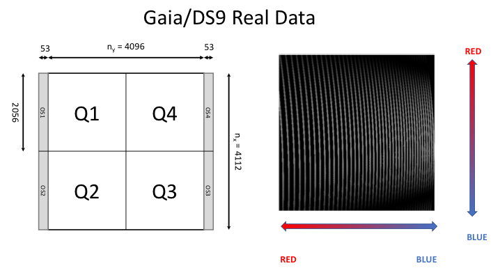
The detector layout (when a raw file is viewed in a standard fits viewer), quadrant numbering and echellogram layout is as follows. A sample image of a science target is below that

Focus sequences were carried out during commissioning using our simultaneously injected ThXe calibration source, and these were used to examine both the focus value that delivers best image quality averaged over the field (525), and the image quality delivered at that chosen value. The simultaneous ThXe spectrum is injected with the same multi-mode fibres used in the Veloce IFU feed, so the FWHM measured from this focus sequence reflects the image quality from the IFU (whereas the LC is injected with an endlessly single-mode fibre that is effectively a diffraction limited point source for the spectrograph).

Image quality at the chosen best focus of 525 encoder units from the ThXe is generally excellent, and everywhere better than 2 pixels in the X direction, and better than 2 pixels in the Y direction in the central 2000 pixels (i.e. Y=1000-3000 corresponding to the spectrograph's FSR).

Veloce Rosso - Detector
The detector is an e2v 4096x4112 device with 15 μm pixels and e2v’s ‘astro multi-2’ coating (its specific model number is CCD231-84-1-E74). In standard operation mode the device is read out from 4 amplifiers in a total read-time of 28s, with a per-pixel read noise of under 4e-. 53 pixels of overscan are acquired at low and high x-pixel numbers for every exposure.
At present the device is only ever used either unbinned (for all science observations), or binned x8 in the Y direction (for fast readouts when doing object acquisition).
Veloce Rosso - Calibration
We have two simultaneous calibration sources available for Veloce. A Laser Comb that injects ~10,000 diffraction limited calibration lines at one end of the pseudo-slit (see below), and a ThXe lamp that injects a ThXe calibration signal at the other end

Laser comb operation
The LC is exposed once at the mid-point of each exposure. It would be fair to say that LC can be a bit tricky to operate. In September it performed mostly flawlessly for over 10 days. In November and January, a little less reliably. We therefore acquire LC+SimThXe exposures regularly throughout the night so that we can always fall-back on the ThXe system if the LC becomes unavailable, while being able to precisely transform between the two systems.
However, does require human supervision to ensure it is ready and operating at the mid-point of each exposure.
Simultaneous ThXe operation
Simultaneous ThXe turns on and off completely reliably. To ensure the same nett exposure for every frame, we use a standard 3 x 2s exposure pattern in each image. The lamp is turned on for 2s at the start, middle, and end of every frame. Note that this does mean the ThXe does not "burn in" in the way that Doppler programs typically require - however, for our purposes it is much more critical that ThXe is the same in every exposure, than it is that it is perfectly burned in. The critical aim here is to have the ThXe (or LC) solve for only a few terms in each exposure (i.e. a differential shift and plate scale changes in the dispersion and cross-dispersion directions), not a complete wavelength solution. The complete wavelength solution comes from nightly deep LC sequences.
Spectrograph stability
Initial tests on the Sep 2018 run indicate our "just enough stabilisation" strategy seems to be working. The spectrograph is stable to ~0.1mbar in pressure and < 10mK in temperature. LC observations show this results in drifts of ~ 4m/s in the echellogram, which the comb is able to differentially calibrate and remove to less than 0.1m/s.
Arc Atlases
Arc atlases to help observers identify lines in the ThXe and ThAr arc lamps have been prepared. The PDF files are large, but they cover the full range of every order, with Th lines selected for precision velocities from the atlass work of Michael Murphy et al (2016). The full atlases can be downloaded, and a sample page is shown below. m numbers are the actual echelle order numbers and "Order" numbers are the orders numbered from 1 at the left hand edge of the image.
-
• CURE ThAr Atlas (thar_atlas_2pp.pdf) and Line List (thar_lines_fibre_01_as_of_2018-11-09.dat)
-
• CURE ThXe Atlas (fib_thxe_atlas_2pp.pdf) and Line List (thxe_lines_fibre_01_for_20180918.dat)

Veloce Rosso - Fibre Feed Sky-to-Pseduo-Slit
Fibres are laid out on the pseudo slit so that they appear as follows on the detector

where the fibre numbers map to the sky as follows (the white numbers are fibre numbers, the red numbers are estimated relative flux for this particular exposure). The IFU spacing between hexagonal micro-lenses is 0.5" (flat-to-flat).

In order to pack so many fibres onto such a long slit, the spacing between fibres is only slightly larger than the fibre sizes. This is a different strategy from that used by traditional IFUs. However, its important to note that we expect every fibre in the main Veloce IFU to see the same starlight. So while there may be cross-talk, it is cross-talk from the same stellar source.
For more details on the fibre feed design see Case et al. (2018)
References
Case et al. (2018), SPIE Astronomical Telescopes and Instrumentation VII, 107026E
"VELOCE's novel IFU-fitted fibre feed" doi.org/10.1117/12.2312939
Gilbert et al. (2018), SPIE Astronomical Telescopes and Instrumentation VII, 107020Y
"Veloce Rosso: Australia's new precision radial velocity spectrograph". doi.org/10.1117/12.2312399 or arXiv:1807.01938