How the clarinet measurements were made

| Acoustics of the clarinet |
How the clarinet measurements were made |
 |
A computer synthesises the signal and outputs it via an audio interface (Motu 828) to a power amplifier and loudspeaker. A conical horn matches the speaker to a waveguide (7.8 mm internal diameter) for delivery to the impedance head. The impedance head is mounted at a position near the tip of the reed in a fitting that seals to the mouthpiece, with no reed present. Measurements are made in a well-insulated room with low reverberation time. The effect of the reed is discussed below.
In the impedance head, three microphones are placed at positions along the waveguide. From the phase and amplitude differences among them, the reflection coefficient and thus the acoustic impedance is calculated.
Three reference impedances, none of them having a resonance, are used. One is a 'semi-infinite' cylindrical waveguide: a straight, stainless steel pipe of 7.8 mm internal diameter. Its impedance is therefore purely resistive. Its length of 42 m was determined by the width of the Physics building. At 200 Hz, a tube of this diameter has an attenuation coefficient of 0.11 m-1 = -1.0 dB.m-1 [1] so the echo returns with a loss of 80 dB or greater. (The dynamic range of the instrument is a little greater than 80 dB, but the precision is less than this. The echo returning during calibration coincides with a frequency component of the input which is 80 dB or more greater, and so can be ignored.) Its impedance is therefore resistive, with resistance equal to its characteristic impedance, Rref = 8.5 MPa.s.m-3. Swagelok fittings are used to connect the elements. The 'semi-infinite' pipe is enclosed in a plastic pipe for sound insulation, and the plastic pipe is mounted above the bearers of the ceiling. The use of a frequency independent reference impedance improves the signal-to-noise ratio over the whole range, and means that the calibration does not depend upon theoretical assumptions about wall losses. Another calibration is an infinite impedance: ie a rigidly closed end. Another is a large flange. The system is described in more detail in the accompanying scientific paper [2].
We measure the complex impedance and store the data as magnitude and phase. However, in the files shown on this site, only the magnitude is shown.
The reed is an acoustical compliance which is, for the sake of this analysis, in parallel with the clarinet [3]. A value corresponding to a volume of 1040 microlitres of air is added algebraically.
Because sound spectra depend very strongly on parameters determined by the
player, by the radiation pattern of the clarinet, and by recording conditions,
sound spectra recorded for human players can only be regarded as examples. The
obtaining of examples typical of playing by a clarinettist under realistic,
musically comfortable conditions are not consistent with obtaining exactly repeatable
spectra. Sound spectra were measured at a distance of about 1 m directly
in front of the player in a recording studio. The player, Catherine Young, is
an accomplished clarinettist who has played with UNSW orchestra and now with
the City of Sydney Wind Ensemble.

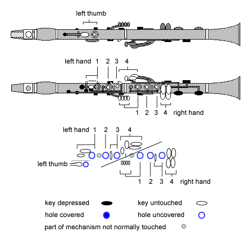
Figure 1. Fingering and acoustic schematic diagram for the clarinet.
Contact: Joe Wolfe / J.Wolfe@unsw.edu.au |